Chapter 12 Solutions
Problems: 5,13,19,27,39,47; 12,16,26,32,52,69; 71
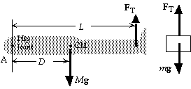
5.  We choose the coordinate system shown, with
positive torques clockwise.  We write
St = I a about
  the point A from the force diagram for the leg:
   StA = MgD - FTL = 0;
    (15.0 kg)(9.80 m/s2)(0.350 m) - FT(0.805 m),
  which gives   FT = 63.9 N.
  Because there is no acceleration of the hanging mass,
  we have
    FT = mg,  or   m = FT/g = (63.9 N)/(9.80 m/s2) =  6.52 kg.
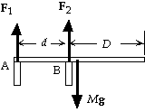
13.  We choose the coordinate system shown, with positive torques
  clockwise.  We write St = I a about the support point A from
  the force diagram for the cantilever:
     StA= - F2d + Mg1/2 (d + D) = 0;
    - F2(20.0 m) + (1200 kg)(9.80 m/s2) 1/2(20.0 m + 30.0 m) = 0,
  which gives F2 =         1.47 x 10⁴ N.
  For the forces in the y-direction we have
    SFy = F1 + F2 - Mg  = 0,  or
    F1 = Mg - F2 = (1200 kg)(9.80 m/s2) - (1.47 x 10⁴ N) = - 2.94 x 10³ N (down).
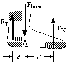
19.  Because the person is standing on one foot, the normal force on the
  ball of the foot must support the weight: FN = Mg.  We choose the
  coordinate system shown, with positive torques clockwise.  We write
  St = I a about the point A from the force diagram for the bone in the foot:
       StA= FTd - FND = 0;
    FTd - FN(2d) = 0, which gives
    FT = 2FN = 2(70 kg)(9.80 m/s2) =       1.4 x 10³ N (up).
  We write SFy = may from the force diagram:
    FT + FN - Fbone = 0, which gives
    Fbone = FT + FN = 3FN = 3(70 kg)(9.80 m/s2) =       2.1 x 10³ N (down).
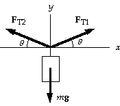
27.  Because the backpack is at the midpoint of the rope, the
  angles are equal.  The force exerted by the backpacker is
  the tension in the rope.  From the force diagram for the
  backpack and junction we can write
    SFx = FT1 cosq - FT2 cosq = 0,  or  FT1 = FT2 = F;
    SFy = FT1 sinq + FT2 sinq - mg = 0,  or
      2F sinq = mg.
  (a)  We find the angle from
      tanq = h/(1/2)L = (1.5 m)/(1/2)(7.6 m) = 0.395,  or  q = 21.5°.
    When we put this in the force equation, we get
      2F sin 21.5° = (16 kg)(9.80 m/s2), which gives F =       2.1 x 10² N.
  (b)  We find the angle from
      tanq = h/(1/2)L = (0.15 m)/(1/2)(7.6 m) = 0.0395,  or  q = 2.26°.
    When we put this in the force equation, we get
      2F sin 2.26° = (16 kg)(9.80 m/s2), which gives F =       2.0 x 10³ N.
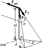
39.  From the symmetry of the wires, we see that the angle between a
  horizontal line on the ground parallel to the net and the line from
  the base of the pole to the anchoring point is q = 30°.  We find the
  angle between the pole and a wire from
    tanb = d/H = (2.0 m)/(2.6 m) = 0.769, which gives b = 37.6°.
  Thus the horizontal component of each tension is FT sinb.
  We write St = I a about the horizontal axis through the base A
  perpendicular to the net from the force diagram for the pole:
    StA= FnetH - 2(FT sinb cosq)H = 0,  or
    Fnet = 2FT sinb cosq = 2(95 N) sin 37.6° cos 30° =      1.0 x 10² N.
47.  The pressure needed is determined by the bulk modulus:
    DP = - B DV/V0 = - (90 x 109 N/m2)(- 0.10 x 10⁻²) =       9.0 x 10⁷ N/m2.
  This is (9.0 x 10⁷ N/m2)/(1.0 x 105 N/m2 · atm) =       9.0 x 10² atm.
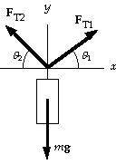
12.  From the force diagram for the hanging light and junction we can write
    SFx = FT1 cosq1 - FT2 cosq2 = 0;
      FT1 cos 37° = FT2 cos 53°;
    SFy = FT1 sinq1 + FT2 sinq2 - mg = 0;
      FT1 sin 37° + FT2 sin 53° = (30 kg)(9.80 m/s2).
  When we solve these two equations for the two unknowns, FT1 , and FT2 ,
  we get        FT1 = 1.8 x 10² N,  and FT2 = 2.3 x 10² N.
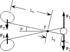
16.  Because FT = FB , from the symmetry we see that F1 = F2 .
  We choose one handle as the system and write St=Ia
  about the hinge P:
  StP = FTL1 cosq - F2L2 cosq = 0, which gives
  F2 = FTL1/L2 = (11.0 N)(8.50 cm)/(2.70 cm) =      34.6 N.
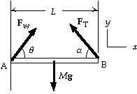
26.  We choose the coordinate system shown, with positive torques
  clockwise.  We write St=Iaabout the point A from the
  force diagram for the beam:
    StA = - (FT sinq)L + Mg1/2L = 0;
    - FT sin 40° + (30 kg)(9.80 m/s2)1/2 = 0,
  which gives      FT = 2.3 x 10² N.
  Note that we find the torque produced by the tension by finding
  the torques produced by the components.
  We write SF = ma from the force diagram for the beam:
    SFx = FWx - FT cosq = 0;
      FWx - (2.29 x 10² N) cos 40° = 0, which gives FWx = 175 N.
    SFy = FWy + FT sinq - Mg = 0;
      FWy + (2.29 x 10² N) sin 40° - (30 kg)(9.80 m/s2) = 0, which gives FWy = 147 N.
  For the magnitude of FW we have
    FW = (FWx2 + FWy2)1/2 = [(175 N)2 + (147 N)2]1/2 = 2.3 x 10² N.
  We find the direction from
    tanq = FWy/FWx = (147 N)/(175 N) = 0.84, which gives q= 40°.
  Thus the force at the wall is       FW = 2.3 x 10² N, 40° above the horizontal.
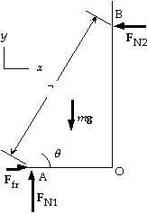
32.  We choose the coordinate system shown, with positive torques
  counterclockwise.  We write St=Ia about the point A from the
  force diagram for the ladder:
    StA = mg(1/2¬) cosq - FN2r sinq = 0, which gives
    FN2 = mg/2 tanq.
  We write SFx = max from the force diagram for the ladder:
    Ffr - FN2 = 0, which gives Ffr = FN2 = mg/2 tanq.
  We write SFy = may from the force diagram for the ladder:
    FN1 - mg = 0, which gives FN1 = mg.
  For the bottom not to slip, we must have
    Ffr <= msFN1 ,   or  mg/2 tanq ? ?smg,
  from which we get tanq >= (1/2 ms).
  The minimum angle is        qmin = tan-1(1/2 ms).
52.  We find the maximum compressive force from the compressive strength of bone:
Fmax = (Compressive strength) Area = (170 x 106 N/m2)(3.0 x 10-4 m2) =      5.1 x 10⁴ N.
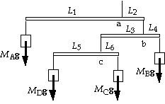
69.  All elements are in equilibrium.  For the C-D pair,
  we write St=Iaabout the point c from the force diagram:
    Stc = MCgL6 - MDgL5 = 0;
    MC(5.00 cm) - MD(17.50 cm) = 0,  or  MC = 3.500MD.
  The center of mass of C and D must be under the point c.
  We write St=Iaabout the point b from the force diagram:
    Stb = MBgL4 - (MC + MD)gL3 = 0;
    (0.735 kg)(5.00 cm) - (MC + MD)(15.00 cm) = 0,  or
    MC + MD = 0.245 kg.
  When we combine these two results, we get      MC = 0.191 kg,  and  MD = 0.0544 kg.
  The center of mass of B, C, and D must be under the point b.   For the entire mobile, we write
  St=Ia about the point a from the force diagram:
  Sta = (MB + MC + MD)gL2 - MAgL1 = 0;
    (0.735 kg + 0.245 kg)(7.50 cm) - MA(30.00 cm) = 0, which gives       MA = 0.245 kg.
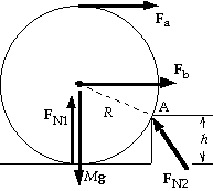
71.  (a)  The cylinder will roll about the contact point A.
We write St = IAa a about the point A:
      Fa(2R - h) + FN1[R2 - (R - h)2]1/2 - Mg[R2 - (R - h)2]1/2 = IAa.
    When the cylinder does roll over the curb, contact with
    the ground is lost and FN1 = 0.  Thus we get
      Fa  = {IAa + Mg[R2 - (R - h)2]1/2}/(2R - h)
        = [IAa/(2R - h)] + [Mg(2Rh - h2)1/2/(2R - h)].
    The minimum force occurs when a = 0:
      Famin = Mg[h(2R - h)]1/2/(2R - h) =       Mg[h/(2R - h)]1/2.
  (b)  The cylinder will roll about the contact point A.
    We write St = IAa about the point A:
      Fb(R - h) + FN1[R2 - (R - h)2]1/2 - Mg[R2 - (R - h)2]1/2 = IAa.
    When the cylinder does roll over the curb, contact with
    the ground is lost and FN1 = 0.  Thus we get
      Fb  = {IAa + Mg[R2 - (R - h)2]1/2}/(R - h)
        = [IAa/(R - h)] + [Mg(2Rh - h2)1/2/(R - h)].
    The minimum force occurs when a = 0:
      Fbmin =       Mg[h(2R - h)]1/2/(R - h).


