PH337 Electronics
Experiment #8
OPERATIONAL AMPLIFIERS Part II LAB
OBJECTIVES
To familiarize you with op-amps used as:
- inverting amplifiers;
- current to voltage converters;
- integrators.
DISCUSSION
APPARATUS
- DC power supply with multiple outputs
- 741 operational amplifier integrated circuit chip
- oscilloscope
- prototype board, capacitors and resistors
- function generator
PROCEDURE
Part Two: Current to Voltage Converter
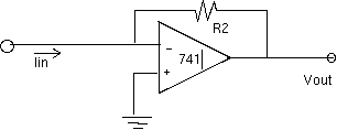
- There is one less resistor in this basic circuit than in the inverting amplifier. Build
the circuit as shown in figure 1 below:


Note: the schematic is less detailed than last week's, since you are now experienced in
properly biasing an op amp. If in doubt, look at last week's schematic. Note and record the
output voltage. (It probably won't be zero!)
The gain is much higher in this circuit, and therefore any small residual voltage that
appears at the input terminals will be amplified much more. There are two techniques for
dealing with any offset voltage:
- (a) Use an external resistor between V2 and ground; or
- (b) Use the offset features built into the Op Amp itself.
We will use both methods in this experiment.
- Add a resistor to the non-inverting input as shown in figure 2.

Try different resistors for the additional resistor Rb. Suggested values are
500 kOhm -- 1 MOhm. See if the output comes closer to zero.
- Then add a potentiometer as shown in figure 3:

Its important that the center contact of the potentiometer be connected to pin 4,
i.e. the -15 Volt side of the 741 Op Amp. Now you should be able to zero out the rest
of the output voltage by adjusting the "pot".
- Check to verify that your output voltage = I x R2. You can do this by generating a 1 microamp
with external resistors and the seperate power supply. See the suggested circuit in figure 4:

After verifying that you have an amplifier that allows you to measure 1 microamp with 0.001 microamp
resolution, you can applyh this circuit to a typical measurement problem in physics: measuring the
"photo current from a photo-tube" as a function of the voltage across the tube.
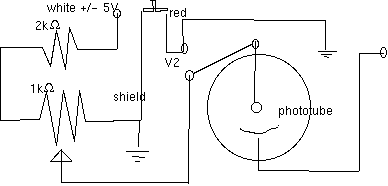
- Connect the input of your Op Amp current converter to the Photo-electric effect module as
shown in figure 5:


By applying a +5V to the Photoelectric module, the anode is positive, thus attracting the
electrons and increasing the current.
When you reverse the polarity to -5V, the anode can be made negative, the electrons are
repelled and eventually stopped when the voltage reaches a great enough value.
- With +5 V connected to the module, adjust V2, the voltage across the phototuve. Do this with no
light on the tube. Then allow the room light to fall on the phototube. Adjust V2 from 0 to maximum
and record both V2 and V1, the output of the Op Amp.
- Repeat with -5V connected to the module. This time you only need to adjust V2 from 0 to approximately -1V.
- Plot your data to see how the photo-tube behaves. Be sure to label your photo-tube current
in microamps.
- Take another few data points with twice the light falling on the photo-tube. Comment on the
value of V2 when both curves intersect or closely approach I = 0 microamps! What is the
significance of this?


